General Dimensional Tolerances For Sheet Metal Formed Parts

Engineering Drawings Gd T For The Quality Engineer Mechanical Engineering Design Mechanical Engineering Engineering Symbols

Iso 2768 General Geometrical Tolerances And Technical Drawings Plianced Inc
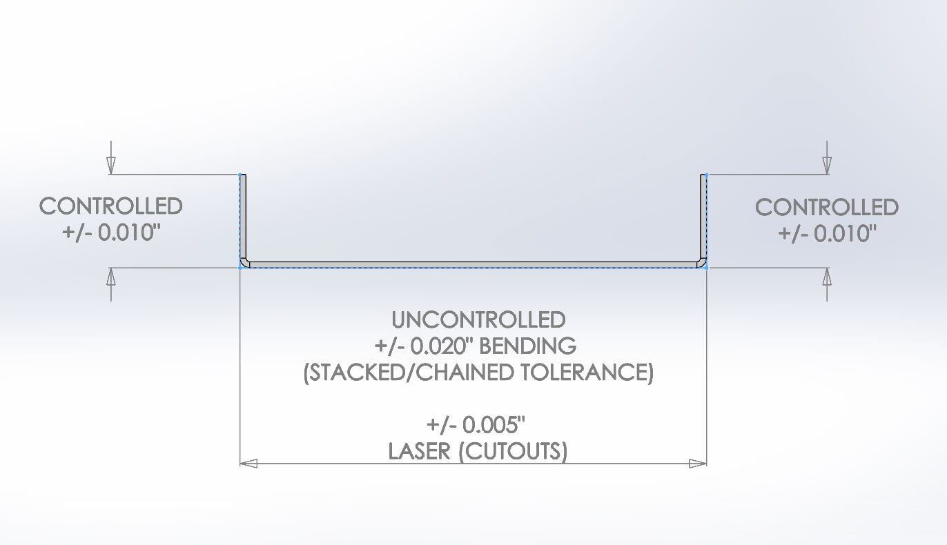
Sheet Metal Bending Tolerances

Pdf Tolerance Transfer In Sheet Metal Forming

Gd T 101 An Introduction To Geometric Dimensioning And Tolerancing Fictiv Hardware Guide

The Vector Stencils Library Dimensioning And Tolerancing Contains 45 Symbols Of Geometric Dimensions Geometric Tolerancing Geometric Symbols Design Elements

Furthermore the parts formed by press working from sheet metal mean those which have been formed by press working of punching bending and drawing from sheet metal and do not include those formed by shear working from sheet metal.
General dimensional tolerances for sheet metal formed parts.

Gd T Symbols Mechanical Engineering Design Mechanical Design Geometric Tolerancing

Sheet Metal Design Guide Geomiq

Geometric Tolerances Investment Castings To Precise Geometric Tolerances Milwaukee Precision Geometric Tolerancing Geometric Mechanical Engineering Design

Gd T Symbols Reference Guide From Sigmetrix Engineering Symbols Mechanical Design Mechanical Engineering Design
Source : pinterest.com
